> DDS Function Signal Generator
> Digital Multimeters
> Distortion Analyzer
> Four Probe experiment
> Function Generator
> IC Testers
> LCR Meters
> Oscilloscopes
> Power Supplies
> Pulse Wave Frequency Meter
> Signal / Function Generator
> Storage Oscilloscopes
> Two Probe Setup
> Withstand Tester
> General Physics Equipments
 
- Digital Micro Volt Meter
- Digital Nano Ammeter
- Digital Pico Ammeter
- Digital Gaussmeter
- Magnetic Field Measurement Apparatus
- Study of Dieletric Constant & Curie Temp of Ferroelectric Ceramics
- e/m Experiment
- Planck’s Constant by Photoelectric Effect
- Determination of Planck’s Constant by means of LED’s
- Frank Hertz Experiment
- Ionisation Potential Set-up
- Measurement of Magnetoresistance of Semiconductors
- Two Probe Method for Resistivity Measurement of Insulators
- Electron Spin Resonance Spectrometer
- Study of Thermoluminescence of F-centres in Alkali Halide Crystals
- Hall Effect in Metals
- Dependence of Hall Coefficient on Temperature
- Apparatus for the Measurement of Susceptibility of Paramagnetic Solution by Quinck's Tube Method
- Apparatus for the Measurement of Susceptibility of Solids by Gouy’s Method
- Magnetic Hysteresis Loop Tracer
   
> TEKON INSTRUMENTS
  - T100 Network Cable Detector
  - T550 Power Quality Analyzer
  - T560 Power Quality Analyzer
  - T600 Txr Turn to Ration
  - T610 Txr Analyzer
  - T650 ESS Diagnostic
  - T700 Ind. Robot Diagnostic
  - T800 EV-HEV Diagonstic


General Physics Equipments
Ionisation Potential Setup - IP01
   

Introduction 

The electrons in the atoms have discrete stationary states. Franck and Hertz in 1914 describes the first observation of quantized excitation from one quantized state to another one year after N. Bohr published his theory of hydrogen atom. His method depends on detecting the on-set of inelastic collisions between electrons and atoms of the gas under study. The experimental tube in this measurement is essentially a triode filled with the vapour of the experimental substance. The electrons emitted by the heated filament of the tube are accelerated by the positive potential VGK between the cathode and the grid. The grid is a wire mesh which allows the electrons to pass through. The anode A is maintained at a fixed potential VGA slightly negative with respect to the grid.


Frank and Hertz in 1914 set out to verify these considerations.

In the experiment the electron current is measured as a function of the voltage VGK . As VGK increases, the energy of the electrons increases, and more and more electrons reach the anode. The anode current increases. The collisions between the electrons and the atoms are elastic. As VGK further increases, the energy of the electrons reaches the threshold for the excitation of the atomic electrons from the ground state to the first excited state, and the collisions between the electrons and the atoms become inelastic. The colliding electrons lose energy and are not able to overcome the negative potential VGA and the anode current decreases. The potential VGK at the decrease is equal to the first excitation potential of the atom. 


Operating Principle


In the present ionization potential measurement, the traditional Franck-Hertz set-up as described above has been altered to detect the threshold for ionizing inelastic collisions. The experimental tube is a tetrode filled with argon, the experimental substance. Figure 1 shows the basic circuit diagram. The electrons emitted by the heated filament are accelerated by the potential VG2K between the cathode and the grid G2. The grid G1 helps in minimizing space charge effects. Both the grids consist of wire mesh and allow the electrons to pass through. The anode A is maintained at a potential slightly negative with respect to the cathode. The electrons are never able to reach it. It is ready to receive positive ions if they have been created in the tube. The on-set of anode current therefore signifies the creation of positive ions, i.e. the on-set of ionizing inelastic collisions between the electrons and the argon atoms. In the experiment the electron current is measured as a function of the voltage VG2K . As this voltage increases, the electron energy goes up. But as long as this energy is less than what is required to ionize the atom, the ions are not created, and the anode current remains equal to zero. The inelastic collisions leading to the excitation of argon atoms are immaterial because no ions are created there in and the anode current remains unaffected. The potential VG2K at the on-set of the anode current is equal to the ionization potential. As VG2K further increases, more and more electrons undergo ionizing collisions and the anode current increases. When VG2K reaches a value twice that of the ionization potential, it is possible for an electron to ionize an atom half way between the grid and the cathode, lose all its energy, and then gain anew enough energy to ionize another argon atom. The anode current beginning at this value of VG2K shows a faster increase with VG2K as now there is a larger number of ions reaching the anode.

Ionization Potential Set-up, Model IP - 001, consists of the following:

  • Argon filled tetrode
  • Filament Power Supply
  • Power Supply for VG1K
  • Power Supply for VKA
  • Power Supply for VG2K
  • Saw tooth waveform for CRO display
  • Multirange Voltmeter
  • Multirange Ammeter

All this is housed in a cabinet with meters and adjustment knobs on the front panel. The set-up can also directly display the anode current variation with VG2K on the oscilloscope screen. It can thus be used as a laboratory experiment as well as for demonstration to a group of students.

Analysis of Data

Point by point data for the anode current with VG2K changing in steps of 1 V at VG1K equal to 1.5 V and VKA equal to 3.0 V are shown in Figure 2. The on-set of the anode current and the point where the slope of the current changes can be determined by locating the points of intersection of the lines as shown in Figure 2. These points are at 15 V and 31 V respectively. The former corresponds to the ionization potential and the later for the ionization again. The average value of the ionization potential thus found is 15.5 eV compared with the accepted value of 15.6 eV.


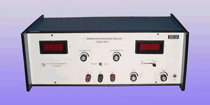


Figure: 2 Plot of anode current vs VG2K in the Ionization Potential Set-up


* Products not listed can be ordered as per request.
* Model number may subject to change without intimation